Airborne Inspection Payload Systems
Mechanical design for helicopter and light-aircraft inspection payloads
Role
CAD / Mechanical design / Manufacturing documentation
Main products
HELIUX MAX, HELIUX LITE, LITE stabilizer
Work included
Large CAD assemblies, CNC machined and sheet metal parts, FDM/SLS/SLA 3D printed parts, sensor fixtures, aircraft mount interfaces, electronics packaging, airflow and load simulations, prototypes, manuals, drawings, and design reviews.
Main contribution
Helped evolve inspection payload hardware from early prototypes into refined, manufacturable commercial systems for aircraft-based inspection and mapping.
Overview
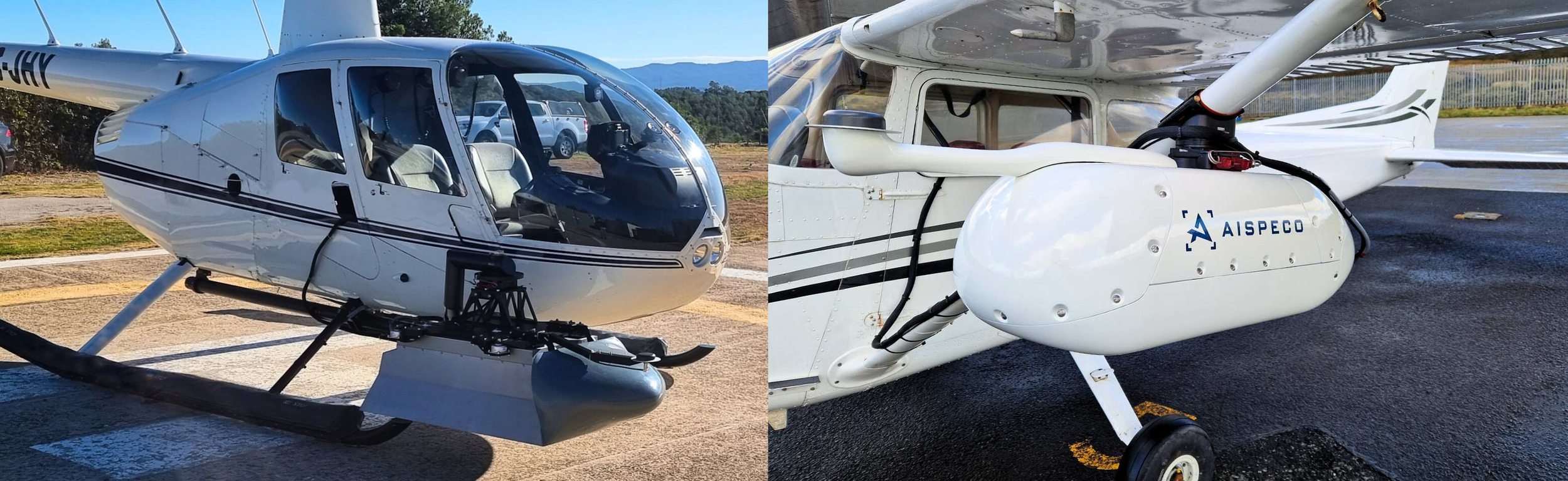
At AISPECO, I worked on airborne inspection payload systems used for helicopter and light-aircraft data collection. These systems integrated cameras, LiDAR, IMU/navigation hardware, electronics, aircraft mounting interfaces, protective covers, and vibration-sensitive sensor assemblies into compact field-ready mechanical platforms.
My work covered HELIUX MAX, HELIUX LITE, and the LITE stabilizer system, with responsibilities growing from CAD modelling and manufacturing documentation into broader mechanical design, simulation, prototyping, design review, and product refinement.
Systems covered
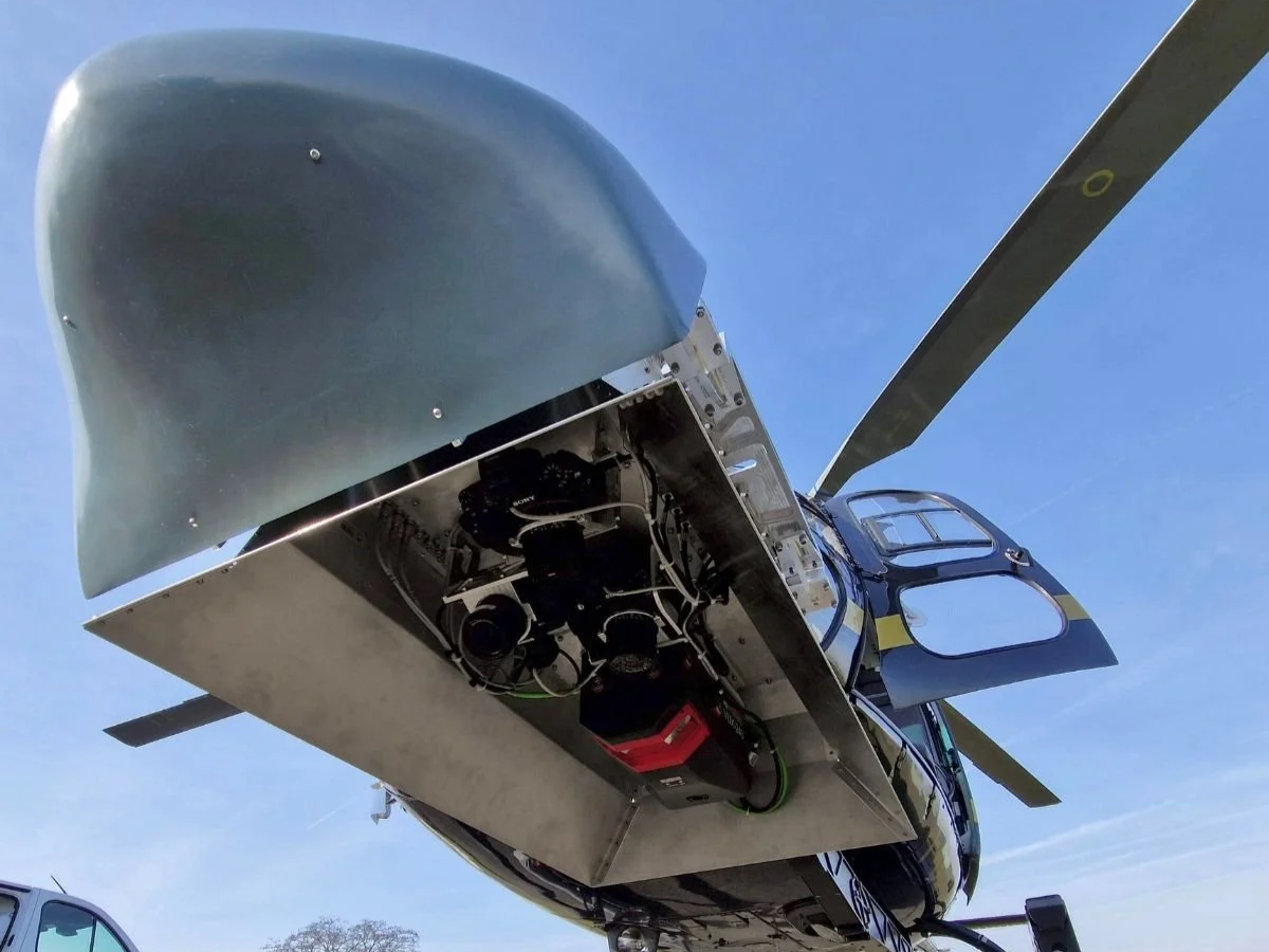
Heliux max
Helicopter-mounted multi-sensor inspection payload developed for larger aircraft-based inspection and mapping missions. The system focused on higher payload capacity, certified helicopter mount integration, configurable sensor layouts, wind protection, and robust mechanical packaging.
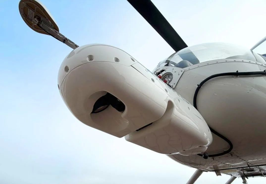
Heliux Lite
Compact inspection payload developed for light aircraft and smaller helicopter platforms. The system focused on reduced size and weight, certified mounting adaptability across multiple aircraft types, compact sensor packaging, electronics integration, and manufacturable pod architecture.
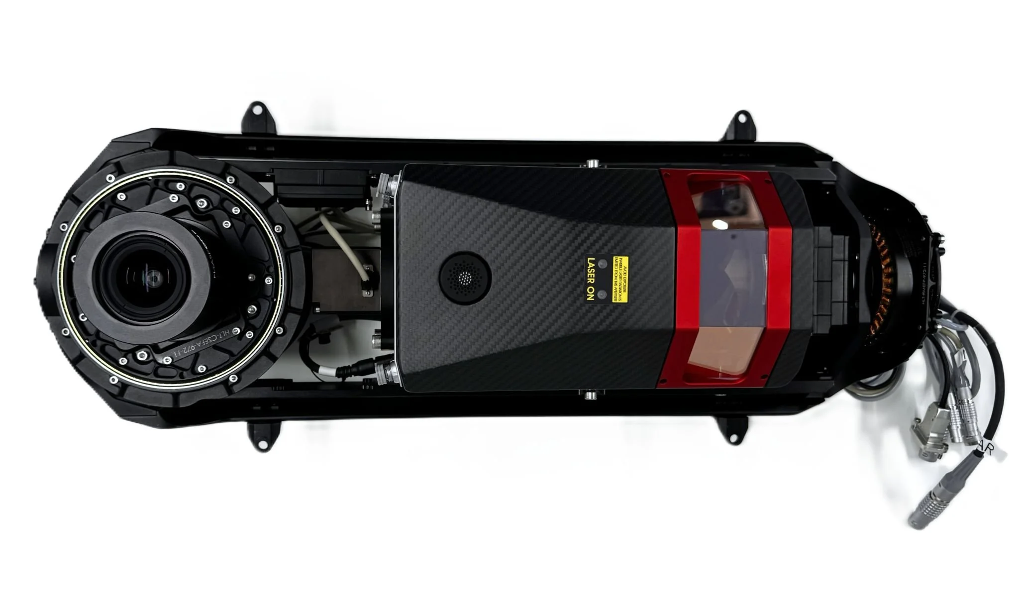
LITE Stabilizer
Stabilized sensor platform developed for the HELIUX LITE system. The subsystem was designed to improve sensor stability during aircraft motion through yaw/roll axis stabilization and later mechanical refinement.
Heliux max
Helicopter-mounted inspection payload platform
MAX V1 — Early architecture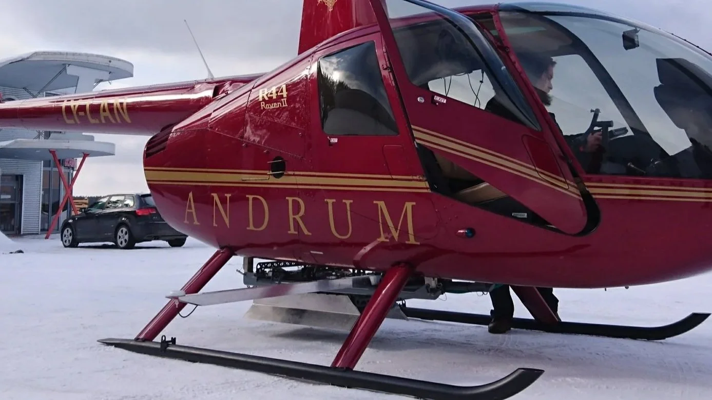
MAX V2 — Refined system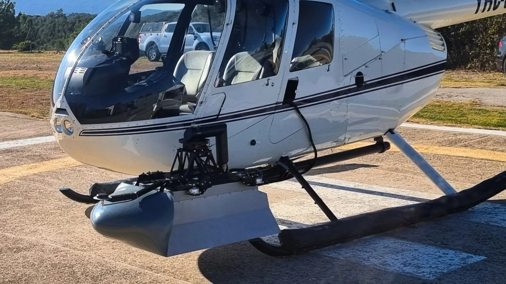
HELIUX MAX was the larger helicopter-mounted payload platform I worked on at AISPECO. It was designed around a rigid enclosure frame carrying cameras, LiDAR, IMU/navigation hardware, electronics, connectors, protective covers, and aircraft mounting interfaces.
My work on MAX started during the early V1 system, where I was mainly responsible for CAD assembly, detailed modelling, drawings, and manufacturing files under senior engineering direction. By MAX V2, my role had expanded into more direct mechanical design input, simulations, documentation, packaging, and product refinement.
The project is a useful example of my progression from CAD-focused work into broader mechanical design responsibility on a real commercial aircraft-mounted system.
MAX System overview
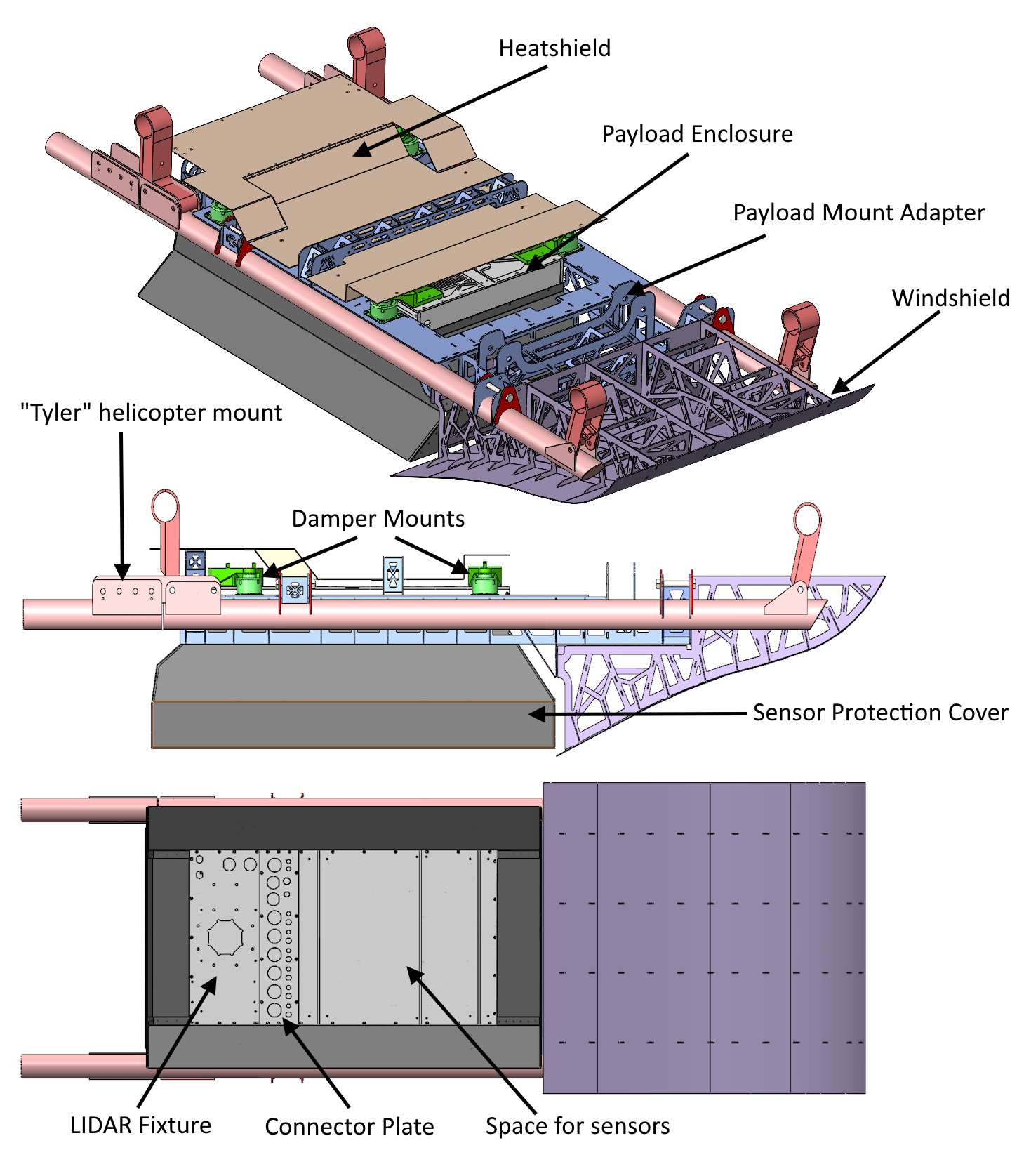
MAX V1 — Early architectureThe main V1 → V2 development was not a single redesign, but a set of mechanical refinements across mounting, protection, enclosure layout, and sensor integration.
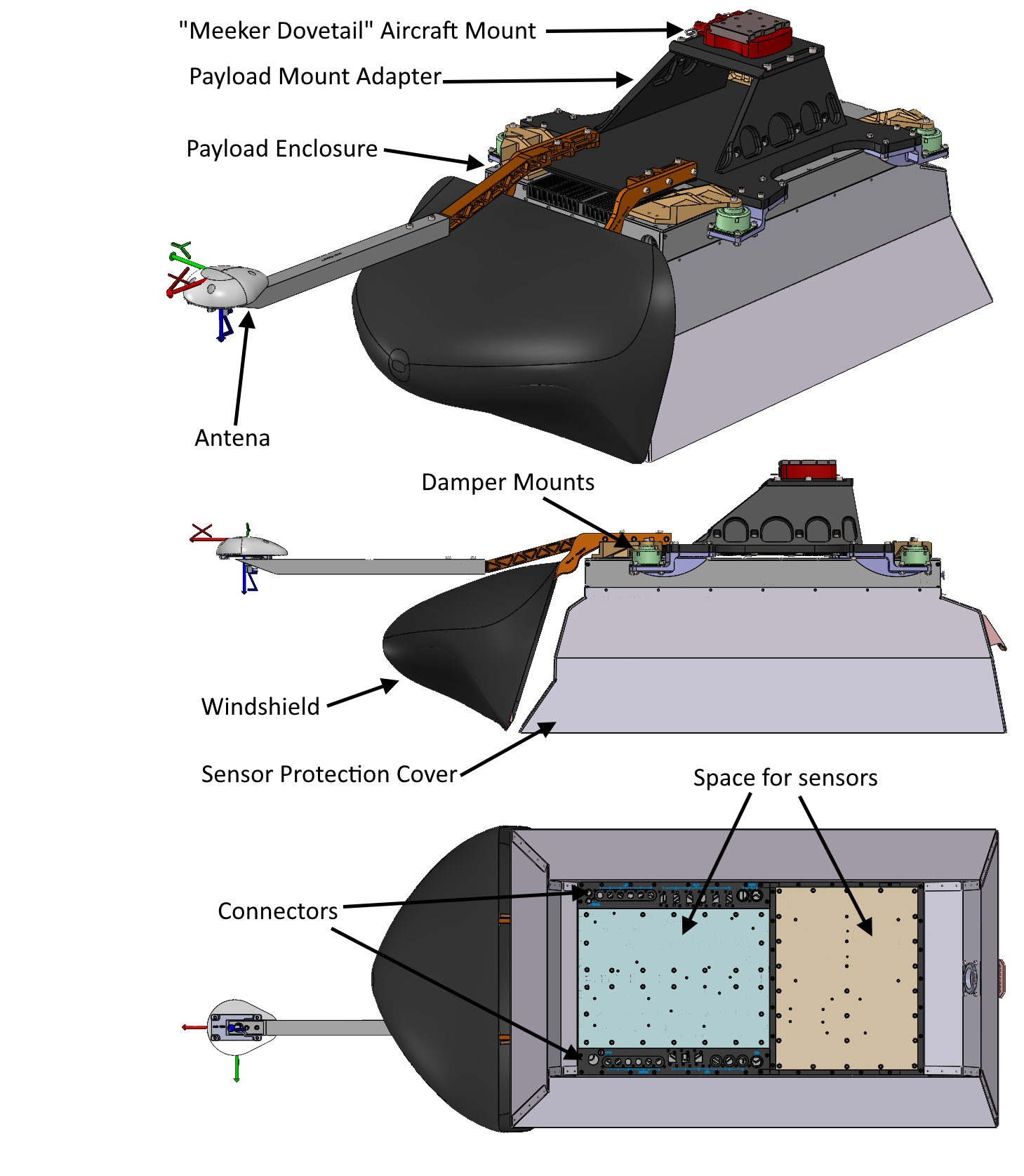
MAX V2 — Refined systemKey Engineering areas
Mounting architecture
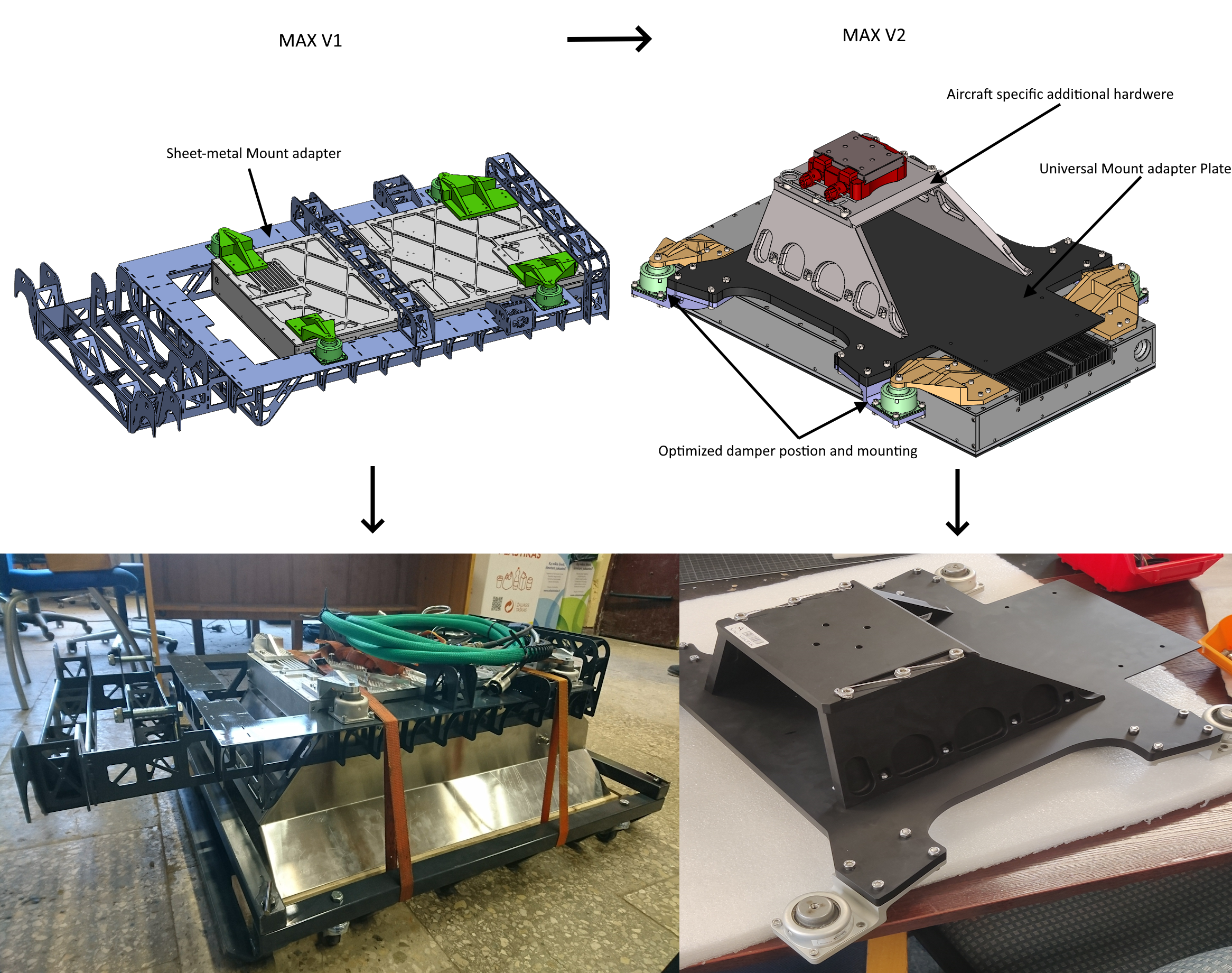
MAX V1 used a welded sheet-metal mounting adapter designed for one specific Tyler mount configuration.
For MAX V2, the mounting system was redesigned into a modular CNC-machined adapter system. A main adapter plate connected to the payload through four dampers, while aircraft-specific hardware could be added depending on the mount system. The same plate also worked as a heat shield, integrating payload protection into the mounting structure.
This made the system more adaptable across different aircraft and mount configurations, while improving repeatability and product refinement.
Protection and airflow
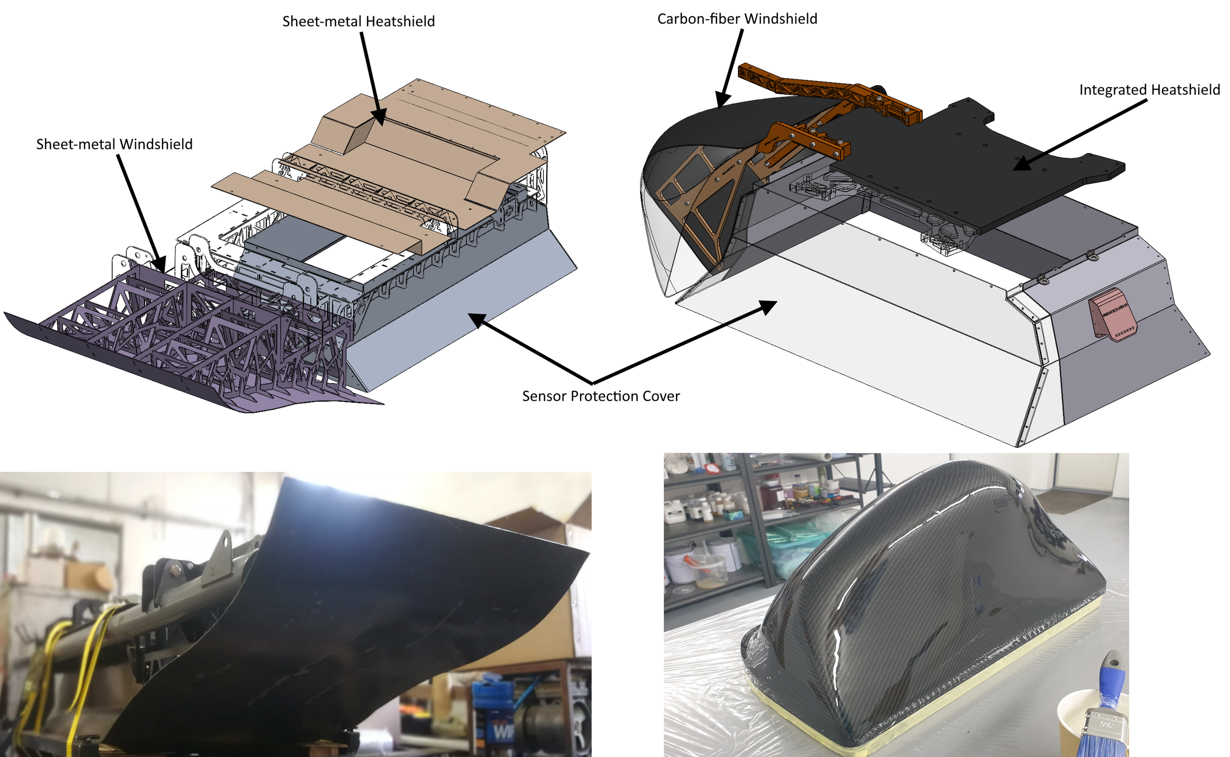
MAX V1 used sheet-metal protective parts around the payload, including the windshield, heat shield, and sensor protection cover.
For MAX V2, the sensor cover was modified to support wider fields of view and larger sensor configurations, while keeping the same general protection concept. The windshield was redesigned as a carbon fiber part, with internal aluminum brackets for structural support. I designed the mold and supported the first prototype manufacturing process.
The heat shield function was also integrated into the redesigned aircraft mounting and damper hardware, reducing separate parts and improving system integration.
Payload enclosure and sensor packaging
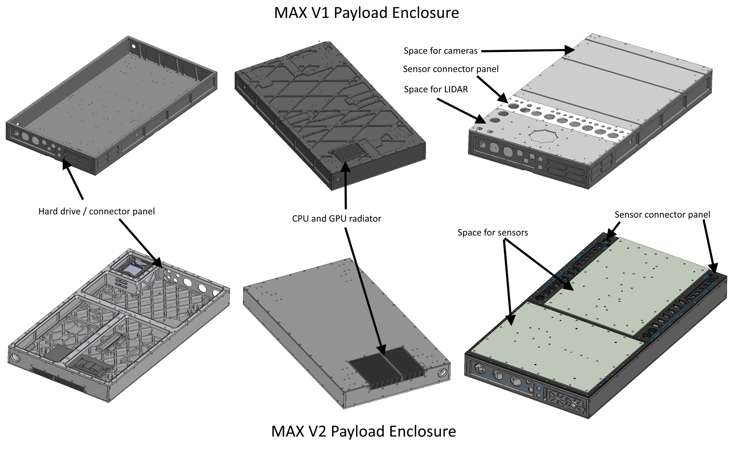
Both MAX versions used CNC-machined payload enclosures, but V2 redesigned the layout around cleaner sensor and electronics integration. The updated enclosure added larger configurable sensor areas, redesigned connector panels, improved internal packaging, and integrated CPU/GPU cooling.
This made the payload easier to adapt for different sensor setups while improving serviceability, connector access, and overall system definition.
MAX system progress Results
HELIUX MAX shows my progression from CAD-focused implementation on an early payload system into broader mechanical design responsibility on a more refined commercial aircraft-mounted platform. Across V1 and V2, my work covered CAD assemblies, machined and sheet-metal parts, mounting architecture, sensor and connector packaging, airflow/protection development, simulations, manufacturing documentation, and product refinement.